
Repair DeLonghi Alice EMK4 Espresso Moka Coffee maker
Date: November 2012
Problem:
This type of espresso, moka coffee maker is commonly found in Italy. I had it for over six years with very light use. One day, it could not power on, showing only garbled display on the LCD when I pressed the power button. Eventually nothing would show at all on the LCD, the LED instead would light up and blink and there was also a humming noise. Unfortunately, with the electronics controlling the brewing, it is not possible to make a cup of coffee without troubleshooting and repairing it.
Warning: This is purely an experiment to see if it is possible to make the coffee maker to function again, the method is not recommended for normal use, do not try it unless you know what you are doing. This is not an advice or tutorial, and I am not responsible for anything that happens good or bad if you try this.
Diagnosis:
The bottom cover on the base is held by several security screws. Fortunately, I have the right security screw bits to open it.
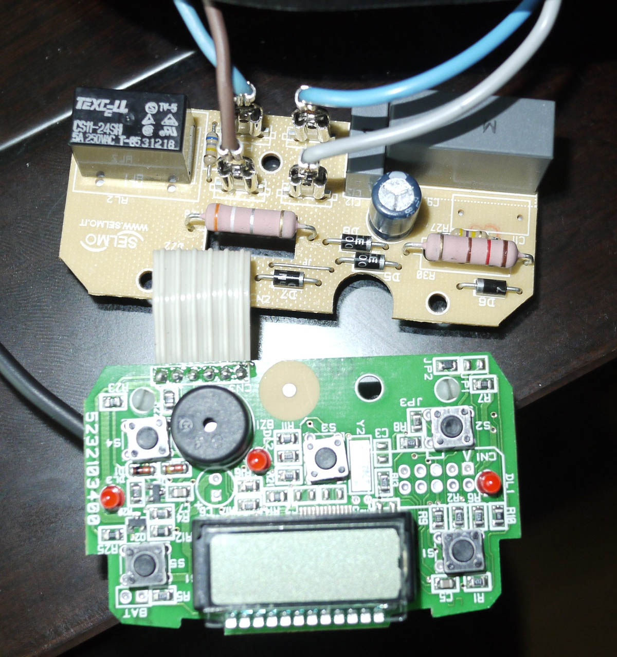
In the base of the unit, there are two circuit boards connected to each other by a ribbon cable. The power supply is on one board and the microcontroller circuit with the display and push buttons on the other. A quick inspection showed one electrolytic capacitor which does not seem to be swollen at the top or leaking, although that does not necessarily mean it is in good condition, but at least it is not a certain, obvious cause.
Although nothing shows on the LCD, the LED light up, which means at least 3V is being delivered to the circuit.
On the power supply side, there is no transformer to step down and isolate the voltage. It is also not a switched mode power supply with high voltage transistor. Instead, it uses a film capacitor based transformerless power supply, which is uncommon in electronics, but often found in appliances because of the space- or cost-saving design. Since they have to minimize the size of the base, it makes sense to eliminate additional components when possible.
Since this coffee maker is designed with a timer in mind, the designer assumes that most people would leave it plugged in most of the time. A transformer based power supply is resistive, that means that the energy is consumed as heat across a voltage dropping resistor (such as the transformer's resistance itself), while a capacitive power supply has little energy loss or heat dissipation because the voltage is dropped across a voltage dropping capacitor.
Lacking two transformers to isolate the two sides of the power supply, the appliance must have a ground connection to the outlet for safety reason, which this coffee maker has. The choice of capacitor connected to the mains also makes a difference to the safety.
There are two classes of AC capacitors used in this application, Class X and Y. Class X capacitor connects from line to line while Class Y capacitor connects from line to ground. When a Class X fails, it does not expose anyone to electrical shock, where as a Class Y failure could. Two class X2 capacitors are used (400V 0.47uf, and 400 47pf or 0.047uf). They are rated to resist a high surge in electricity from the mains without damaging the power supply or the user.
There are four diodes together function as a bridge rectifier, and the one electrolytic capacitor is used to filter the pulsating DC. There is one zener diode (not seen in the photo, behind the ribbon cable) is used to regulate the filtered DC. If I am not mistaken, the 1/2-watt big resistor is used to limit the current through the zener diode.
Considering there is a buzzing noise, and the LED are on when I press the power button, and the relay is responsible for taking a low voltage signal input and power on the unit. I decided to begin with the relay.
Repair:
First, I replaced the relay with a similar one (12V to 5A, 240V, or 12V to 10A 120V), but it did not solve the problem.
I took measurement of the voltage across each of the two class X2 film capacitors. The 400V 0.47uf capacitor showed only 3~4V, which is not enough to power the 5V components on the electronics circuit. So I replaced the 35V 220uf electrolytic capacitor, and I took the measurement again across the bigger 400V 0.47uf capacitor and it showed 12V, which I think is sufficient to drive the 12V relay and the rest of the electronics. However, that still did not solve the problem.
I did not want to spend too much time troubleshooting individual components further, since the goal is just to brew coffee, and the timer is a function that I never used in the past. I decided to remove the entire electronic boards from the base unit and connect the wires directly to the base socket that sits the coffee pot. If you think about, the coffee maker is essentially a water heater, this model just has an extra electronics unit that controls the timing to power on the brewing. A normal water heater is very simple, it has a base which connects to the mains power line, and the pot has connects to the base to allow electricity to conduct to the heating element to heat the container.
In this case, once I plug the coffee maker to the outlet, it will begin heating the water and brewing the coffee immediately. The question is, what happens when it is done brewing since there is not a power off switch. One way to solve this problem is to add a power switch. Another way is to simply unplug it.
Result:
After correctly connecting the necessary wires and carefully reassembling the pot and base, as soon as I plug in the coffee maker, it begins to brew coffee. Although it is functional again, here are some important considerations in term of safety.
What if I forget to unplug the coffee maker? Would it overheat and become a fire risk? It turned that inside the bottom of the pot unit, wrapped by a heat-resistant clear plastic sleeve, there is a resettable thermostat, which will cut off the current when the themostat reaches certain temperature. It will reset after the temperature cools enough.
I originally thought it to be a resettable thermal cut-off fuse. That means, when it is cool at room temperature, it naturally conducts electricity when a current is applied to it at power on. As current passes through it and increase its temperature, it will become an open fuse once the temperature passes certain limit, hence shuts off the electricity to the pot and avoids overheating. It should have a hold current rating, which means, as long as it remains plugged in, the fuse will remain open. Once it cools down, the fuse will reset when the coffee maker is unplugged and plugged in again. This part I am not too certain, as I cannot look up the exact part number used. After some research, I think a thermostat is more likely because it is commonly used in water heaters (kettles) and the coffee maker is similar in design.
Now, another question: if the thermostat resets itself when the temperature cools, does that mean the current will conduct again when the coffee maker is still plugged in? If it does, that means it will heat up the pot quickly and trip the thermostat again, until it cools down again and restart the cycle until the coffee maker is finally removed from the power source. This is a possible scenario considering that this coffee maker does not have an off switch after the modification. Today, most water kettles and coffee makers have a thermostat-trigger automatic power off switch, but it does not apply to this one.
It is better to unplug the unit as soon as the machine finishes brewing, or install a power switch instead of relying on the thermal cut off fuse or thermostat.
Update: Later when I had more time to play with the power supply board, I found the zener diode is defective as it conducts in both directions (it should conduct only in one direction, to simplify it). Diodes don't fail as often as electrolytic capacitors, but they fail sometimes, so it should be tested at the diagnostic stage. Had I replaced this zener diode, I would probably not have needed to resort to a barebone unit.
Comments? Suggestions? Please leave it on my YouTube video page.